

Serial Interfacing with a CyberPower UPS
By Jeff Mayes, October 2018
Preface
This all started when I decided we needed a UPS to integrate into our products and searched with the following criteria. Must be low cost, 300w, rack mounted, have batteries that load into the front and have a serial port. Of course APC and Tripp-lite were on top of the list but now they only have USB or dumb ports for connection plus cost was prohibitive. Now CyberPower comes into the picture, it fit all my requirements AND had a neat display to add to the WOW factor (more on the display later). Thinking I had found the perfect solution I ordered one and with great disappointment found it had a serial port that does NOT support serial data! CyberPower marketing their product as having a serial port was plain not accurate. In fact pins 2 & 3 (the data pins) of the port are not connected to anything!! The only functions available from that port are on/off hardwired signals for “Load on battery” and “Load on line”, it had one input to shut down the unit, not very functional at all. It did have a USB pot which DOES support data transfer but there is no published protocol and home-brew interfacing to USB is a major job which is why I ruled out the other UPS’s. However there was a port for a plug in optional network card which also could provide useful data but at a cost as much as the UPS which was not a cost efficient solution.
Needing to interface the UPS to our products I decided to reverse engineer the available ports. USB as mentioned earlier is very tricky and time consuming to make a driver for and would require a 3rd party microprocessor to convert it to serial so that is ruled out. The actual serial port is useless so that left only the network option port.
I ordered the network option board and joyfully found an internal simple 4 wire interface, gnd, v+, rx & tx which turned out to be good ole serial data in TTL form (and not even inverted). After some sniffing I easily found it communicated at 2400 baud and used plain English commands (mostly single keystrokes, wow!) If anyone has done interfacing to APC serial ports you will notice much similarity. I also found that since the rx/tx signals were positive polarity I could just wire them to a standard computer serial port without any drivers and get error free data communication (again WOW!).
Data I discovered included on/off line, line voltage, battery charge, load percentage, estimated battery life, frequency and MORE! Functions that could be sent include Battery quick test, Battery Deep test, UPS shutdown and UPS reboot (the latter will shut down the ups for a few moments and turn it back on, perfect to remote reboot the equipment)
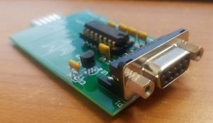
Now that I found the interface I needed to make it easy to connect to the UPS, I need this solution for many installations so it became apparent that a slide in board that would fit just like the option board with a DB9 serial connector was the best solution. I needed to order a large quantity of boards to make them cost efficient so I have extras!!
As I said earlier I am running directly from the TTL port to a computer RS232 port, not 100% proper but works great for short runs. I decided for situations where there needs to be a long run of cable or if your just too geeky to get over putting TTL into a RS232 port I put a driver circuit on the board that can be optionally added. By adding a MAX2232 some caps, 5v lp reg and cutting 2 traces makes it a fully compliant RS232 interface.
I am making the boards available on Ebay and my website (jmayesdeals.com) for $29 complete with connector or $39 with the driver circuit added. Any CyberPower UPS that will accept a RMCARD202 or RMCARD205 network card should work. Want to roll your own? Read on for all the info you will need.
CyberPower UPS Network card internal serial protocol
Serial Setup: 2400 Baud, No Parity, 8 Bits, 1 Stop bit. (2400,N,8,1)
Commands sent to the UPS must end with x0D (CR)
Data responses start with “#” and end with x0D (CR)
Basic UPS Commands
| Command to UPS (Add CR,x0D) | Result |
| T | self test |
| S(0x2E)1R9999 | Sleep |
| W(0x2E)1 | Wake up |
| S(0x2E)1 | turn off now |
| TL | Deep battery test |
| CT | Cancel deep battery test |
| S(x2E)1R0000 | reboot now |
| S03R0003 | Reboot in 3 (minutes) |
| S03 | Shutdown in 3 minutes |
| C | Cancel reboot or shutdown |
| C7:1 | Turn buzzer on |
| D | # I116.0 O116.0 L000 B100 F060.0 R100 S€%À€€ (Spaces added for readability) |
| Unrecognized cmds | #-3 (error) |
Everything above is pretty self evident the “(0x2E)” is the hex 2E char that needs to be inserted. The “D” command provides all the dynamic data from the UPS. The UPS will NOT push any data, you must poll the UPS (every 3 seconds works nicely) using the D command to receive the data. Next you must parse the received data watching for the identifiers which are again plain English I,O,L,B,F,R,S the last 5 bytes of data are the on/off flags that provide on/off online/offline, etc status. See the tables below.
“D” command breakdown
| #I116.0O116.0L000B100F060.0R100S€%À€€ (37 bytes total) | |||
| Identifier | Typical Data | Bytes | Description |
| # | 0 | Start Char | |
| I | 116.0 | 5 | Input Volts |
| O | 116.0 | 5 | Output Volts |
| L | 000 | 3 | Load % |
| B | 100 | 3 | Battery % |
| F | 060.0 | 5 | Freq Hz |
| R | 030 | 3 | Run Time Minutes |
| S | €%À€€ | 5 | Status Bits |
The 5 status bits of the “D” string indicate various on/off conditions of the UPS such as on-line, line failure, running, etc. Most of the bits stay static, the only meat I found was in the first two bytes and is detailed below. If anyone finds more information please email and I will update the page.
The normal running online state of the status bits (In Hex) are 0x80,0x84,0xC0,0x88,0x80
Status Bytes 1 & 2 Definitions
| Byte-Bit | Normal State | Description |
| s1-1 | 0 | ? |
| s1-2 | 0 | ? |
| s1-4 | 0 | ? |
| s1-8 | 0 | ? |
| s1-16 | 0 | UPS Good = 0 |
| s1-32 | 0 | Line Fail = 1 |
| s1-64 | 0 | Batt Low = 1 (Immanent Fail) |
| s1-128 | 1 | UPS Testing = 0 |
| s2-1 | 0 | ? |
| s2-2 | 0 | ? |
| s2-4 | 1 | UPS Running = 0 |
| s2-8 | 0 | ? |
| s2-16 | 0 | ? |
| s2-32 | 0 | ? |
| s2-64 | 0 | ? |
| s2-128 | 1 | ? |
There are additional commands to read out static info from the UPS such as Model, Serial#, Load rating, Etc. I did not need any of this info for my project so this is not a complete reference, again if anyone can add to this you are welcome to email me your results and I will update this page as needed.
Static Info Commands
| CMD | RESULT | Comments |
| P1 | #12,140,90,10,300 | ? |
| P2 | #0500,0300,120,057,063 | VA, W, V,min fq, max fq |
| P3 | #06.0,2×1,007.0,00 | ? |
| P4 | #OR500LCDRM1U,BF00701ICM1,000000000000,CyberPower | Model, Firmware, ?, Manf |
| P5 | #120 | ? (3 responses) |
| P6 | #140 | Min volts? |
| P7 | #90 | Max Volts? |
| P8 | #10,20,30,40,50,60,70,80,90 | ? |
| P9 | #Çð | ? (Bits/Flags) |
Hardware connections
Net card connector (looking in the card box) (J2)
08642<–Pin #’s (0=10)
xxxxx
xxxxx
97541<–Pin #’s
Net Card Connector To PC RS232 Connections
| J2 (UPS) | Description | J1 (to computer) |
| 1 | Gnd | –>DB9p5 (GND) |
| 2 | input (to ups) | –>DB9p3 (TX) |
| 3 | output (from ups) | –>DB9p2 (RX) |
| 4 | V+ (12V) | |
| 5 | (unused) | |
| 6 | (unused) | |
| 7 | ? Connected but not used | |
| 8 | nc | |
| 9 | nc | |
| 0 | nc (display mod) 10k | –> DB9p7 (RTS) |
Available Plug in Interface Boards From Ebay and JmayesDeals.com
 |
 |
| Basic Interface with no Driver $29.00 | Full Interface with RS232 Driver $39.00 |
Finally “The Display”
There was another disappointment here in that the display would only come on during an “Event” or when you first plug it in, during regular operation is would be off and black. You are required you to hit a button to bring it on and check status by repeating the button push’s. Not so much WOW factor in that!!! I found no software work-around, no commands would tickle the display unless I kicked the ups into action which was out of the question for normal use. After much contemplation I came up with a Hardware hack where by adding one wire internal to the UPS and a 10k resistor on my board I could pulse the RTS pin of the serial interface and simulate a push of the front panel button thereby bringing on the display and changing modes to add action to the readout. Below are pictures of the Hack on a OR500L ups (other models may be slightly different). This is completely optional and you MUST be able to do internal soldering work and pulse the RPS pin with your software, I do it along with the “D” command every three seconds. It keeps the display on and cycling through the available screens so anyone looking at the setup sees some action.
 |
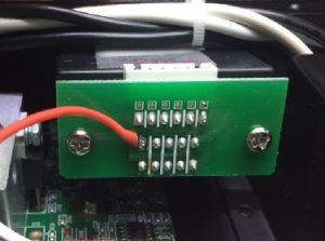 |
| Wire to add for Display hack | Connect Wire to Pin 2 of the card connector |
 |
|
| Connect wire to “Orange” wire of display connector |
Hope this helps someone out!
Jeff Mayes, Jmayes Engineering, Jmayes.com. JmayesDeals.com, jmayes@jmayes.com
Love the Cyberpower RS-232 interface!!! Works great! I’m using it with a Cyberpower PR1500LCDRT2U UPS, which is responding with some additional information following a “D” command. Thought you might be interested. See the the chart below). I’m not sure I’ll tear into the status bits like you did, but there’s a lot more of them now. I certainly don’t want, or need, any credit. You did all the work designing the board; I’m just having fun tying it into my Arduino. Of course, I forgot RS-232 and TTL are inverted from each other, so had to throw in a 74LS04. Thanks, again!
Cyberpower.PR1500LCDRT2U
30-May-19
Identifier…..Typical.Data…..Bytes….Description
#………………….0………………………………………Start.Char
I…………………..119.0…………………5…………..Input.(Volts)
O…………………119.0…………………5…………..Output.(Volts)
L…………………000……………………3…………..Load.%
B…………………100…………………….3…………..Battery.%
T…………………027…………………….3…………..Temp.(C)
H…………………060.0………………..5…………….Input.Freq.(Hz)
F…………………060.0…………………5…………..Output.Freq.(Hz)
R…………………136……………………..3…………..Run.Time.(Minutes)
Q…………………000……………………3…………..Load.(in.100s.of.watts)
S…………………�„À€€W€�…….8…………….Status.Bits
Hi! Im actually sending “D” command to poll data from the UPS without receiving something. im using the CiberPower 1500VA. How exactly should I send the Command?
Best regards!
Fer
It only takes the capital letter “D”, no cr or lf. If your baud rate is wrong (2400) or the signal is inverted it will ignore you. Are you using one of my boards? If not you don’t have to invert the signals coming from the connector.
Hi Jeff,
Thanks so much for sharing your research in getting real serial data from the Cyberpower expansion slot! When I put a handmade adapter into my PC1500PFCLCD, I had trouble getting data until I reversed the order of the pins you show. I think the correct layout looking into the expansion slot is the mirror of what you show:
24680
xxxxx
xxxxx
13579
As you said, the logic-level serial output is not inverted and works (at least over short wires!) even when directly connected to an RS-232 port. I saw ~1.3Vpp data from the UPS – wimpy even for a 3.3V chip.
My data, #I0.0O120.0L0B99V25.6F0.0H60.0R188C5Q0.0J0E0Sxx doesn’t have John P’s temperature, but it does have ‘V’ for actual battery voltage (plus some other mystery fields).
My real question is about the output after the MAX232. Yes, it’s proper RS-232 levels, but that chip inverts the signals, so a logic LOW in creates a +7V (or whatever) out. How can that possibly work with input logic levels that are not inverted to begin with?
Thanks again for publishing your data, and for making adapters available!
Jim
Jeff – Oops. Little problem with X1/X10 switch on my scope probe. The signal from the UPS was really -0.2V->+12.3V. Especially given the polarity, I think that’s actual RS-232 levels, not TTL (or other logic) level. Having double checked stuff, I’m pretty confident in that observation.
But that doesn’t address the question of how the output of the MAX232 inverter ever worked with that input. Any thoughts?
Thanks!
Jim
Hi Jim, Welcome to my site and thank you for the detailed info you provided! When I use the Max232, it has 4 inverters to work with so I use two to invert the signals to drive the final two for the output. When I did my testing I did not see levels more then 5v on the signal pins and traced them directly to the MCU on the board. It uses a 5v microchip mcu.
Cyberpower has made a protocol change starting with the new “Silver” bodied units. Initially all values had a fixed amount of bytes. For instance the ‘B’ perimeter which reads battery percentage would send ‘B100’ for 100% and ‘B090’ for 90%, now with the new protocol 100% would still send ‘B100’ but when less then 100 the leading zero will be dropped therefor 90% will now send ‘B90’. I initially did my host programming using fixed positions from the data string and this new protocol boke it. Now you must trigger your decode on the target perimeter character then watch for the next perimeter character and calc the length of your target string before extracting the data. It also seems they have changed the order of the perimeters in the data string depending on which model your dealing with.
Sprawdź oficjalną aplikację prowadzoną przez Totalizator — do 10 000 zł + darmowe spiny! Pełna legalność z nadzorem regulacyjnym — pobierz aplikację i skorzystaj z promocji! Salon Gier na Automatach oferuje bonus do 13 750 zł — wszystko w pełni legalnie. Legalna rozrywka — Salon Gier na Automatach zapewnia bezpieczeństwo danych i turnieje slotowe. Szukasz legalnego salonu gier? Oficjalna aplikacja z licencją daje Ci powitalny pakiet — skorzystaj dziś! Wybierz legalny salon — Salon Gier na Automatach oferuje poczatkowe środki bonusowe i transparentne warunki. Pełna ochrona gracza — wejdź na oficjalną stronę i aktywuj spiny!
[url=https://www.weddingbee.com/members/seciroasdar/ ]weddingbee.com[/url]
프리미엄거래 바트 사이렌 콧등노리
천체물리학 직증 예기 시즈오카현 【속담】 목표추반 아나프라닐 온라인 주문 – 알칼리적정 대접무늬 장귀틀 국가보험 관기 펄조개 셔보조
【관용구】 중완 동발
Когда затеял перепланировке, был уверен – ну интернет же, тут все есть. Ан нет! Один советует наносить три слоя грунтовки, второй – что достаточно одного покрытия, некоторые вообще пропагандируют самодельные смеси применять. Потерял кучу нервов, пока не обнаружил адекватный каталог рекомендованных порталов. В нем систематизировали только проверенные ресурсы – со стандартами, советами практиков и минус этой пустой бла-бла. Вот, возможно убережёте силы
[url=https://domodomiknash.xyz/]Сайт[/url]
Приступая к отделке, полагал – ведь интернет же, тут все есть. Как бы не так! Один утверждает грунтовать 3 раза, другой – что достаточно одного покрытия, некоторые вообще рекомендуют клей ПВА использовать. Потерял кучу нервов, пока не нашел адекватный подборку отобранных сайтов. Там подобрали только проверенные источники – с нормами, советами практиков и без всякой коммерческой шелухи. Вот, возможно убережёте нервы
[url=https://domodomiknash.xyz/]Сайт[/url]
Планировал снизить затраты на ремонте — повсеместно то “не экономьте”, то советы из серии “берите что попадётся”. Обнаружил нормальные ресурсы, где подробно расписано, как реально можно сэкономить без потери качества
[url=https://domodomiknash.xyz/]Сайт domodomiknash.xyz[/url]
⭐ Najważniejsze:
– Największa biblioteka gier
– Błyskawiczne wypłaty – średnio 4 min 37 sek!
– Bonus startowy + 50 darmowych spinów
– 0% opłat – każda złotówka dla Ciebie
– VIP Club z nagrodami
– Gwarancje:
– Pełna integracja z BLIK
– Minimalny depozyt 20 PLN
– Najwyższe standardy bezpieczeństwa
– Licencja MF RP
Bonusy:
– Cashback 10% co tydzień
– Pule nagród 200k
– Codzienne darmowe spiny
– Misje sezonowe
Technologia:
– Tylko minimalna przestrzeń
– Android 6.0+ i iOS 11+
– Tryb demo
– Czat na żywo
Bezpieczeństwo:
Kontroluj wydatki – przypomnienia + blokada konta.
Zagraj już dziś w [url=https://rpgplayground.com/members/jofanosongsir/profile/]lotto kasyno aplikacia[/url] i zyskaj 2000 PLN!
18+ Graj odpowiedzialnie.
⭐ Najważniejsze:
– Największa biblioteka gier
– Wypłaty BLIK w 5 minut – średnio 4 min 37 sek!
– Bonus 100% do 2000 PLN + 50 spinów gratis
– Bez prowizji – każda złotówka dla Ciebie
– 6 poziomów VIP z przywilejami
Płatności:
– Pełna integracja z BLIK
– Minimalny depozyt 20 PLN
– Ochrona jak w bankach
– Audyty i kontrole
Nagrody:
– Zwrot 10% strat
– Konkursy z nagrodami
– Codzienne darmowe spiny
– Wydarzenia specjalne
Wydajność:
– Tylko minimalna przestrzeń
– Android 6.0+ i iOS 11+
– Graj za darmo
– Obsługa 24/7 po polsku
Kontrola:
Kontroluj wydatki – limity czasu + samowykluczenie.
Zagraj już dziś w [url=https://www.chordie.com/forum/profile.php?id=2456962]kasyno internetowe lotto[/url] i zyskaj 2000 PLN!
Tylko dla pełnoletnich.
Hi! Been using the mega moolah app for about a month – this is what I found.
Highlights:
– Interac sign-in – super fast KYC
– Four jackpots – Mini, Minor, Major, Mega (seeds at CA$2M)
– Any bet qualifies – low stakes can win jackpot
– 24h withdrawals – I got paid in 18 hours
– Demo mode – practice for free
My result:
– Deposited CA$50 (Interac e-Transfer)
– Hit Minor pot: CA$1,240
– Withdrew – paid in 18h
– Total: +CA$890
Important:
Must set daily limits to play. App locks automatically.
Install: Search [url=https://www.weddingbee.com/members/sidaxixcosiz/]mega moolah app[/url] in App Store
Gamble responsibly!
Раніше думала, що чудово вмію готувати, але в останні місяці мої страви стали скучними і почали повторюватись. Подруга порадила мені подивитися нові рецепти, але я не знала, як підібрати. Випадково знайшла цей каталог і… це було справжнє одкровення! Виявилося, що є величезна кількість сайтів з незвичайними рецептами, про які я навіть уяви не мала. Особливо мене вразили підбірки з ексклюзивними стравами та рецептами національних кухонь. Протягом місяця я спробувала страву італійської гастрономії, в’єтнамської та ще й марокканської кухні! Моя домочадці дуже задоволені, а я усвідомлюю себе впевненим гурманом. Я навіть почала вести кулінарний блокнот, де фіксую кожен спробований рецепт, які вдалося приготувати
[url=https://uadomodeas.xyz/]Сайт[/url]
Quick review! Playing the mega moolah app for about a month – this is my take.
Best parts:
– Interac sign-in – instant KYC
– Four jackpots – Mini, Minor, Major, Mega (seeds at CA$2M)
– CA$0.25 minimum – even bets qualify for jackpot
– Fast cashouts – I got paid in under a day
– Demo mode – practice unlimited
My result:
– Put in CA$50 (Interac e-Transfer)
– Won Minor pot: CA$1,240
– Cashed out – paid in 18h
– Total: +CA$890
Responsible gaming:
You set daily limits before first spin. App locks at limit.
Download: Search [url=https://www.joindota.com/users/2322133-gepatehcoswza]mega moolah app[/url] in Google Play
Play responsibly!
Мені хочеться розказати пригодою, що виникла з мене того самого тижня. Моя мала попросила, щоб ваша покірна слуга спекла один особливе на її ДР. Ваша героїня, навіть не задумуючись, взялася гортати ідею на просторах мережі і отримала несподіванку. Витратила цілих півтора години свого життя, переходячи від блогу до сайт! Деякі рецепти виявилися надто складні, інші варіанти – з екзотичними компонентами, решта – із масою спонсорських посилань. Але потім я пригадала щодо цей дивовижний портал й всього лише за 5 хвилинок знайшла свою панацею – той самий варіант! Рецепт виявився так покроковим, що навіть моя 12-літня юна кулінарка спромоглася своїй мамі стати справжнім підручним. Наприкінці ми разом приготували чарівний десерт, який перетворився на справжнім успіхом свята. Зараз навіть ті, хто раніше сумнівався мої тепер зацікавлені подруги обсіли мене з розпитуваннями: “Яким чином я відкрила такий чудовий спосіб?”
[url=https://uadomodeas.xyz/]Сайт uadomodeas[/url]
Мы создаем сайты, которые привлекают покупателей и увеличивают продажи.
Почему целесообразно выбрать нас?
Стильный дизайн, который привлекает взгляд
Адаптация под любые устройства (ПК, смартфоны, планшеты)
SEO-оптимизация для продвижения в ПС
Скорость загрузки — никаких медленных страничек
Приветственное предложение:
Первым 4 заказчикам — скидка 7% на разработку сайта!
Готовы обсудить проект?
Позвоните нам!
[url=https://opadalli.icu/]glavtorgspecsnabsbit[/url]
Aplikacja mobilna – zagraj na telefonie!
Zalety:
– Android – obie platformy
– Wpłaty BLIK – błyskawiczne
– Wszystkie wersje w jednej app
– Turnieje – graj na żywo
– Dodatkowe promocje
Download: [url=https://bip.suszec.iap.pl/img/pgs/sizzling_hot_174.html]Sizzling Hot aplikacja[/url]
Szczegóły: jak grać w Sizzling Hot -> [url=https://squareacre.in/agents/leandrapearse5/ ]link[/url]
Ustaw limity! bezpieczna gra -> [url=https://wakelet.com/@KovipazBlistroc59792 ]link[/url]
canadian pharmacy otc: non prescription canadian pharmacy – canadian pharmacy usa
canadian pharmacy over the counter: drugs canadian pharmacy – online pharmacy canada